

联系我们
齿形滑环式组合密封
关键词:
所属分类:
Performance and Purpose:
Slip ring combined seal is made up of low-friction PTFE composite slip ring and O-ring. It has the advantages of friction resistance, temperature resistance, high pressure bearing ability, high linear velocity, small friction force and long use-life. And which is applicable to dynamic and static seal of hydraulic and pneumatic system in aircraft, metallurgy, petroleum, chemical, textile, food industry and so on.
由低摩擦聚四氟乙烯(PTFE)复合材料滑环与O形圈组合而成的组合密封具有耐磨、耐温、耐压、线速度高、摩擦力小和使用寿命长的特点。适用于航空、冶金、石油、化工、纺织、食品等行业的液压与气动系统的动、静密封。
Advantage
The structure is simple, easy to install and can be used repeatedly
结构简单,安装方便,可重复安装使用
The sealing performance is reliable and adjustable
密封性能可靠,密封性可调节
Different types of PTFE materials(Self pressed PTFE barrel material) can be selected according to the working conditions of sealing environment
自主压制四氟桶料,可根据密封环境工况选择不同类型四氟材料
The working life of dynamic pressure seal is 5 ~ 10 times higher than that of conventional rubber sealing products, and the highest working life can reach dozens of times
工作寿命高,动态压力密封工作寿命比常规橡胶密封制品高5~10倍,最高可达数十倍
It can be used as oil-free lubrication seal
可作无油润滑密封
The friction force is small, and the dynamic and static friction force are equal. The friction force is 1 / 2 ~ 1 / 4 of the O-type rubber ring, which can eliminate the "crawling" phenomenon of motion at low speed and low pressure.
摩擦力小,且动、静摩擦力相等,是O型橡胶圈的1/2~1/4,可消除低速低压下运动的“爬行”现象
Sample of marking
JK3—I A 70 X 5.3
Section diameter d2 of O-ring
Diameter d of piston rod (axis) (Diameter D for sealing hole)
O-ring standard (A-GB/T3452.1-2005; B-GB1235-76; Not mentioned if non-standard)
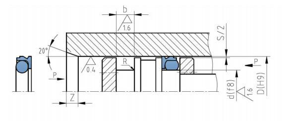
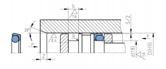
Pistion rod (axis) sealing (Ⅱ-Hole sealing)
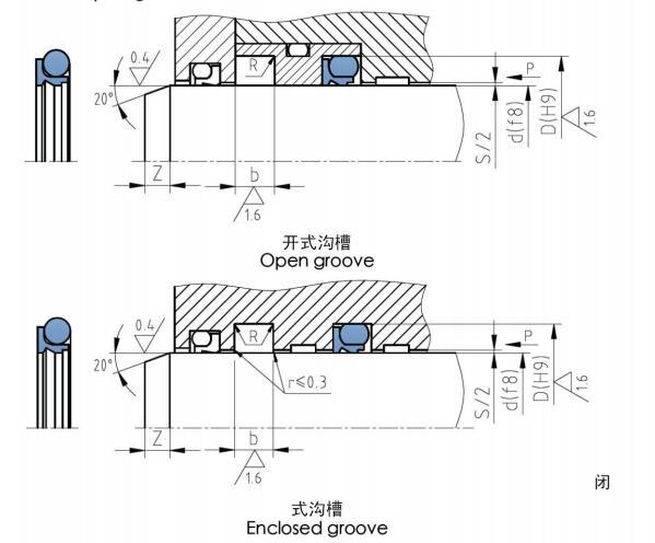
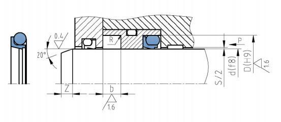
Tooth-shape slip ring combined seal
JK3—Ⅰ沟槽尺寸
JK3—ⅠGroove dimensions
|
轴径 Axis diameter d(f8) |
沟槽底径 Groove bottom diameter D(H9) |
沟槽宽度 Groove width b+0.2 |
O形圈截面直径 Section diameter of O-ring d2 |
内圆角 R |
径向间隙 Radial clearance S≤ |
倒角 Chamfer Z≥ |
|
6~15 |
d+6.3 |
4.0 |
2.65 |
0.2~0.3 |
0.3 |
2 |
|
16~38 |
d+8.2 |
5.2 |
3.55 |
0.3~0.5 |
0.3 |
3 |
|
39~110 |
d+11.7 |
7.6 |
5.30 |
0.4~0.8 |
0.3~0.4 |
5 |
|
111~670 |
d+16.8 |
9.6 |
7.00 |
0.8~1.2 |
0.3~0.5 |
7 |
JK3—ⅠA沟槽尺寸
JK3—ⅠA Groove dimensions
|
轴径 Axis diameter d(f8) |
沟槽底径 Groove bottom diameter D(H9) |
沟槽宽度 Groove width b+0.2 |
O形圈截面直径 Section diameter of O-ring d2 |
内圆角 R |
径向间隙 Radial clearance S≤ |
倒角 Chamfer Z≥ |
|
6~15 |
d+6.3 |
3.7 |
2.65 |
0.2~0.3 |
0.3 |
2 |
|
16~38 |
d+8.2 |
4.6 |
3.55 |
0.3~0.5 |
0.3 |
3 |
|
39~110 |
d+11.7 |
7.0 |
5.30 |
0.4~0.8 |
0.3~0.4 |
5 |
|
111~670 |
d+16.8 |
8.8 |
7.00 |
0.8~1.2 |
0.3~0.5 |
7 |
JK3—Ⅱ沟槽尺寸
JK3—ⅡGroove dimensions
|
缸径 Cylinder diameter D(H9) |
沟槽底径 Groove bottom diameter (f8) |
沟槽宽度 Groove width b+0.2 |
O形圈截面直径 Section diameter of O-ring d2 |
内圆角 R |
径向间隙 Radial clearance S≤ |
倒角 Chamfer Z≥ |
|
14~25 |
D-6.3 |
3.8 |
2.65 |
0.3~0.5 |
0.3 |
3 |
|
26~51 |
D-8.2 |
4.7 |
3.55 |
0.6~0.8 |
0.4 |
3 |
|
52~127 |
D-11.7 |
7.0 |
5.30 |
0.6~0.8 |
0.3~0.5 |
5 |
|
128~500 |
D-16.8 |
8.8 |
7.00 |
0.8~1.0 |
0.4~0.6 |
7 |
|
501~1000 |
D-19.8 |
11.2 |
8.60 |
0.8~1.0 |
0.4~0.6 |
9 |
JK3—ⅡA沟槽尺寸
JK3—ⅡA Groove dimensions
|
缸径 Cylinder diameter D(H9) |
沟槽底径 Groove bottom diameter d(f8) |
沟槽宽度 Groove width b+0.2 |
O形圈截面直径 Section diameter of O-ring d2 |
内圆角 R |
径向间隙 Radial clearance S≤ |
倒角 Chamfer Z≥ |
|
14~25 |
D-6.3 |
3.8 |
2.65 |
0.3~0.5 |
0.3 |
3 |
|
26~51 |
D-8.2 |
4.7 |
3.55 |
0.6~0.8 |
0.4 |
3 |
|
52~127 |
D-11.7 |
7.0 |
5.30 |
0.6~0.8 |
0.3~0.5 |
5 |
|
128~690 |
D-16.8 |
8.8 |
7.00 |
0.8~1.0 |
0.4~0.6 |
7 |
专业从事钢管静水压试验用超高压密封元件研制、生产、销售的科技型生产企业。公司致力于钢管水压试验机用密封元件的研究和生产,拥有较强的专业研发团队及优秀的售后服务人员。先后与国内十余家著名水压试验机设计单位建立合作关系,为其配套设计,生产各种新型密封产品。标准静水压试验要求,性能稳定,使用寿命长,畅销国内及东南亚市场,深受国内外用户的一致好评。


在线咨询
北京建科汇峰科技有限公司
